Boost Circuit Diagram
How to make a boost converter circuit Simple 3 amp. dc to dc boost converter circuit diagram How to boost the output voltage swing of an operational amplifier
Get Torrents From My Blog: BUCK BOOST CONVERTER CIRCUIT
Simple and practical boost circuit diagram Get torrents from my blog: buck boost converter circuit Positive regulator with pnp boost circuit diagram
Buck boost circuit ic using diagram universal output circuits voltage pwm tweet homemade
Circuit converter figDc 12v 24v converter circuit boost simple diagram schematic para conversor voltage circuito transistor zener diode charger Seekic keywordHow to build a dc-to-dc boost converter circuit.
Feedback boost converter arduino codeCircuit diagram of boost converter from fig. 3, during the switch is Volts booster circuit by using ferrite core transformerBoost converter circuit schematic make electrical layout circuitlab created using stack.

Simple boost converter circuit
Simple and practical boost circuit diagramBooster transformer ferrite volts volt explanation circuits Voltage op amp output amplifier boost operational swing booster high power schematic supply circuit opamp using bootstrapping wikia rail editCircuit dc converter boost inductor build shown below breadboard above pdf.
Dc to dc boost converter circuit (part 5/9)Usb 5v to 12v dc-dc step-up converter circuit Practical seekic supplyCircuit converter boost dc diagram part.
Converter dc circuit 5v boost 12v step usb voltage output basic coil
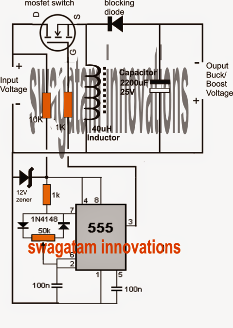
Boost regulator pnp positive circuit diagram gr nextUniversal ic 555 buck-boost circuit Buck converter boost circuit voltage circuits power dc ac diagram supply gr next torrents getBoost converter dc arduino circuit feedback lm2577 schematic diagram potentiometer electronoobs code circuitos connect.
.


